Labels

Saturday, December 30, 2017

Installed antennae and battery bus power: 3 hours


  • Permanently installed transponder and communication radio antennae - However I still need to put sealant around exterior
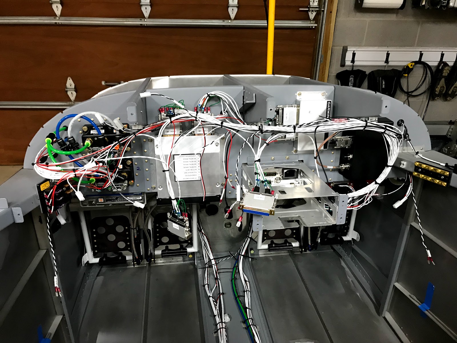
  • Installed wiring for both main and auxiliary battery buses. This consists of a Blue Sea fuse holder mounted on the firewall and 10 awg wire running to the bus bars behind the instrument panel. These wires connect directly to each battery and will provide redundant power for each electronic ignition, the g3x and the electric fuel pump.
  • I also received my 12 volt / 30 amp power supply. I got this unit off of ebay. It's marketed towards ham radio users and provides clean power. Pricing was very reasonable. I connected the cord and used some leftover wire to make leads to connect to the aircraft electrical system.
  • I went ahead and connected the seat heater on the left side. With the new power supply I can run all the avionics and the seat heater for as long as I want. The seat heater worked great with the exception of the indicator LED in the switch. I was able to find a replacement switch on ebay so I ordered several to have a spare for the future.


Power supply hooked to main battery leads:

Main battery bus fuse holder:

Aux battery bus fuse holder (wires will be secured later with cushion clamps)
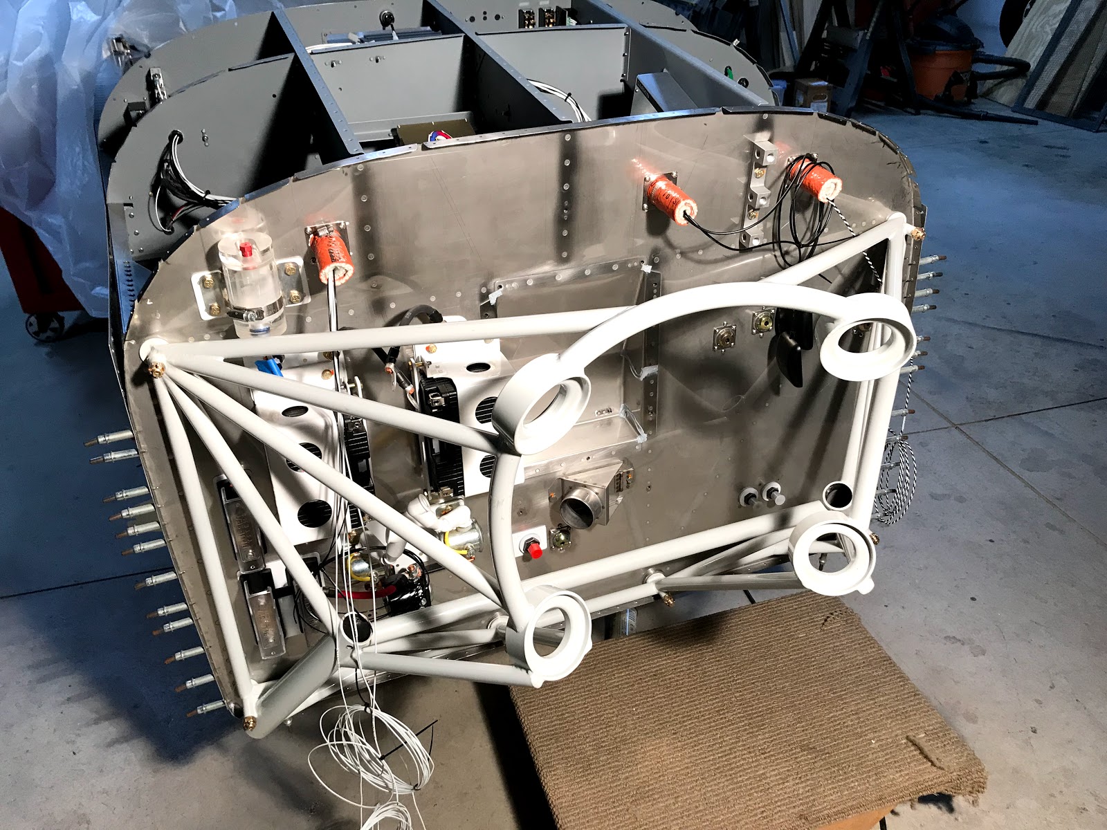
Comm antenna:

Transponder antenna:

Sunday, December 24, 2017

Solved VPX connection and upgraded GTN 650 software: 2 hours


  • I found that the VPX was working but not communicating with the G3X display. I reviewed all the configuration settings then checked the wiring. I found that I had two of the RS-232 pins in the wrong spot. Once I corrected this the VPX data displayed on the G3X MFD. 
  • I downloaded the latest software for the GTN 650 on my PC then transferred it to an SD card - all very straight forward.
  • Everything went well with the upgrade except for the WAAS GPS section it turns out the GPS antenna has to be connected and is also updated. 
  • I went ahead and made the cable for the GPS antenna and connected it - then the software update went fine.


VPX electrical page on G3X and software update on GTN 650:

Saturday, December 23, 2017

Electrical system, VPX and GTN 650 initial power up: 4 hours

Powered on full electrical system including both batteries and VPX. After that I connected the G3X and GTN-650 and powered it all on with no problems :)

  • Made and installed wiring from main feed fuse to VPX - used 6 awg wire
  • Figured out wire routing for main feed and contactor wiring and secured temporarily with wire ties - this will be done with cushion clamps when the inverted oil system is installed
  • Wired main, auxiliary and start contactors
  • Wired start contactor annunciator which included soldering a resistor near the ring terminal
  • Temporarily connected both batteries and powered on system using the instrument panel battery switches.
  • Downloaded VPX windows configurator program and connected to VPX with ethernet cable. I then uploaded my initial configuration to the VPX. I also did some basic system checking but I believe that the G3X needs to be configured before going much further.

All avionics powered on - time to configure:

Batteries and contactors connected:

Using the VPX configurator:

Close up of resistor for start annunciator wire:

VPX main power feed:

Temporary wire routing:

Thursday, December 21, 2017

Installed engine mount and some wiring: 3 hours


  • The majority of the time was spent installing the engine mount. This has six an-6 bolts with castellated nuts and cotter pins. Getting everything to line up in the correct torque range took some time swapping nut, washers etc. The torque range is 160-190 inch pounds. All my bolts were torqued to a minimum of 170 with most closer to 190.
  • I spent some time reviewing eaa videos on cotter pins before I installed the pins.
  • I also finished the short wire connections from the circuit breakers to the hot battery buses and did a couple of the electronic ignition power wires.


Cotter pin detail:

Engine mount "permanently" in place:

Circuit breakers for hot battery buses:

Wednesday, December 20, 2017

Miscellaneous firewall forward and cockpit work: 4 hours


  • Used template to drill holes for glareshield edge trim
  • Installed battery cables. I used silicone terminal boots on the "hot" battery connections.
  • Used the Dremel tool to carefully grind two half circles in the edge of the instrument panel to let the lighting wires pass through.
  • Made a flared tube piece to connect the brake reservoir with the firewall fitting. I think this will work fine but I'm also considering having a short hose segment made when I have my other firewall forward hoses done.
  • Fitted the right landing gear leg into the engine mount. This took a while to figure out and involved cleaning up the inside of the engine mount and removing powdercoat from the gear leg. The Dremel plus the scotchbrite wheel made this easy. I also reamed the bolt holes with a .311 reamer for a close fit on the AN-5 bolt.


Right gear fitted - left should go much faster...

Brake reservoir firewall line:

Notch for panel light wires with half grommet:

Battery cables installed:

Drilling glareshield trim template:

Tuesday, December 19, 2017

Various electrical work: 6 hours


  • Worked on wiring some of the circuit breakers for the electronic ignition
  • Put the forward top skin in place and positioned the glare shield trim to figure out the location of the led lighting strips for the instrument panel
  • While figuring out where the lighting wires will go I noticed some defects on the roll bar powder coat that would be very noticeable. Decided to go back to paint. Started removing powder coat.
  • Made the short cables that connect the batteries to the aircraft grounds and the battery contactors. I used 4 awg welding cable as recommended by the author of the Aeroelectric Connection book. These are very short pieces and the welding cable is very flexible. I also used double wall heat shrink then sealed the exposed ends of the cables with e6000. I used the heavy duty ratcheting crimper and fittings from Stein Air.


Locating position of instrument panel led strips:

Battery cables:

Thursday, December 7, 2017

Finished VPX wiring: 5 hours


  • Wired all the switches on the instrument panel that connect to the VPX.
  • Completed the J1 input connector for the VPX - this completes all VPX wiring. Next step will be configuring and testing the unit.
  • Made ground wire daisy chain for all VPX switches
  • Completed J244 connector for GEA 24 interface box. This connector only has 4 pins used: Take off / go around and autolevel for autopilot and left and right fuel tank quantity.


All VPX connectors complete:

All VPX switch wiring in place (all labeled and organized):

A lot of wires for the J1 connector:

Lighting switches connected to VPX and ground:

Only using 4 pins on this huge connector:

Wednesday, December 6, 2017

Tested G3X aux power circuit and more wiring: 6 hours


  • Ran the wire from the left hot battery bus to the G3X aux power switch and the G3X aux power fuse block.
  • Temporarily installed G3X PFD and MFD displays and made some adjustments to wiring bundles
  • Put a temporary CAN bus terminator on the roll servo wiring
  • Connected my test battery to the left hot battery bus and turned on the G3X aux power  switch - everything powered up perfectly. Both displays booted up and I got flashing green leds on the ADAHRS and the GEA 24 engine interface which indicates good network communication.
  • I upgraded the software for both G3X displays and the PFD automatically upgraded the software for the ADAHRS - very easy.
  • I spent a fair amount of time playing with the G3X system - I'm impressed with all the capabilities!
  • I started working on the final wiring for the VPX which involves wiring for the battery contactors and the switches that are hooked to the VPX.
  • I ran wires for the main and aux battery contactor and the starter annunciator.
  • I also built up a wire to monitor aux battery voltage which requires a resistor to be soldered in line.

G3X looks great!:

G3X aux power and aux battery voltage leads on the left hot battery bus:


Tuesday, December 5, 2017

Finished installing wire harness for G3X: 6 hours

Avionics wiring in place and organized. I'm now ready to test the G3X backup power system.


  • Finished and attached GEA 24 engine data interface power / CAN bus connector
  • Finished and attached both connectors for GMA 245R audio panel - these took a while - many small pins to insert and a bunch of shield grounds to attach to the connectors - all done in the cockpit
  • Used solder splices and sleeves in the cockpit to complete CAN bus connections for both ADAHRS - worked great
  • Finished and attached both power / CAN bus connectors  for the ADAHRS
  • Attached all power, back up power and ground wires for both G3X displays, the ADAHRS and the GEA 24 engine data interface. Also power wires for the remote audio panel.
  • Spent a fair amount of time organizing and cleaning up wiring


ADAHRS and G3X auxiliary power fuse panel on left:

All avionics wiring in place:

CAN bus node using solder splices - very easy:

GMA 245R audio panel connectors (before being organized):

GEA 24 engine data box just has power and CAN bus hooked up for now:

All VPX power connectors are now full:

Monday, December 4, 2017

Progress connecting wire harness: 4 hours

The following work was done over several days:


  • Did initial install of avionics wire harness - lots of loose power and ground wires which will get cleaned up!
  • "permanently" installed GTN 650 connectors and tray
  • Finished GTX 23 transponder connector and mounted to tray
  • Hooked up a variety of power and ground wires for avionics
  • Connected VPX to G3X RS-232 link and completed VPX J1 connector


Hard to see but the black object is the VPX J1 connector:

GTX 23 connected and ready to test:

GTN 650 tray with connectors and spaghetti explosion (will be organized):

GTN 650 back plate with connectors ... a lot going on there: