Labels

Aileron (31) Avionics (72) Canopy (80) Cowl (28) Electrical (40) Elevators (36) Empennage (94) fiberglass (22) Firewall Forward (58) Flap (43) Fuel System (23) Fuel Tank (4) Fuselage (156) Horizontal Stabilizer (25) Interior (27) Landing gear (10) Paint Schemes (2) Parachute (30) prop (2) Rudder (13) Vertical Stabilizer (14) Wing (133) Wing tip (2) Wiring (18)
Showing posts with label Fuselage. Show all posts

Wednesday, August 22, 2018

Cockpit and cowling work

Two inch extension on top cowl curing. (This extension should allow the cowl to fit the longer engine mount.)

I used some flashing material for the extension mold.

Installed canopy roller tracks. Black delrin pieces will get trimmed for exact fit with tip up slider mod.


Riveted F-704K "upright capstrip" in place on left and right side. (light gray primer part just under roll bar)


Very happy with instrument panel placard from Front Panel Express.

Thursday, August 16, 2018

Fuselage forward top skin is on!

  • The last "major" piece of riveting is done. I riveted the forward top skin on using a combination of driven rivets and a large number of Cherrymax structural pull rivets.
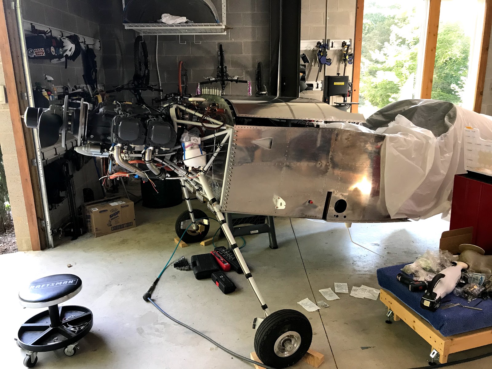
  • Before doing this I went over all the wiring and wheeled the fuselage outside to test the gps antennae.
  • I also designed an instrument panel placard and programmed the G3X engine information system parameters. I'm still very impressed with the G3X Touch system.


Forward top skin is finished. Roll bar is partially installed. Very happy with the black powder coat.

It's difficult to get a good picture in the garage!


Riveting in progress. The Cherrymax rivets are noticeable close up but will be less so once the aircraft is painted. 


I also designed a placard for the instrument panel which I ordered from Front Panel Design. This placard has the required experimental aircraft passenger warning, instructions for the ballistic parachute and a stick grip button legend. It also will hide an access hole through the panel.

Early mock up of placard:

Primed and painted the exposed part of the inside of the forward top skin:

Making the cutouts for the defog fans:

Monday, January 29, 2018

Elevator controls: 4 hours


  • Adjusted stick grips, applied loc tite and torqued set screws.
  • Positioned forward push pull tube in tunnel.
  • Clamped elevator in neutral position and temporarily attached aft push pull tube.
  • Adjusted aft tube to bring the bell crank vertical.
  • Adjusted auto pilot pitch servo linkage for bell crank position.
  • Adjusted forward push pull tube for slightly forward stick (5-6 degrees) in neutral elevator position. I also put the seat in and checked hand position and elevator travel. Both of the push pull tubes fit almost perfectly and only required small adjustments.
  • Permanently bolted forward push pull tube to bell crank.


Bell crank with aft and forward push pull tubes and pitch servo:

Forward push pull tube attached:

Monday, August 28, 2017

Riveted forward fuselage structure, started installing avionics: 5 hours


  • Riveted sub-panel to canopy deck - used a combination of msp-42 pull rivets and driven rivets
  • Riveted ribs to firewall - used hand squeezer and rivet gun
  • Installed firewall sensor manifold - this will hold transducers for oil, fuel and manifold pressure.
  • Installed mounts for VPX ECB (electronic circuit breaker) and EFII ignition computers - these mounts were fabricated from aluminum angle and also help to stiffen up the sub-panel structure
  • Installed mounts on to remote transponder tray then installed the assembly including the GTX-33 transponder
  • Installed the dual GSU-25 ADAHRS computers (air data attitude heading reference system!) - the combination of the sub-panel doubler and the transponder mounts make this side of the sub-panel very stiff which is what you want for the ADAHRS units.
  • Installed the GDL-39R ADS-B receiver.
  • I was going to mount the VPX unit but first I will need to make a standoff to keep one of the right brake lines from rubbing on it.


Sub-panel with ADAHRS (left), GTX-33 (lower left), GDL-39R (right) and VPX (lower right):

Electronic ignition computer and VPX ECB mounts:

GTX-33 transponder tray mounted:

Transponder tray in progress:

Sensor manifold:

Riveting in progress:

Friday, August 25, 2017

Forward fuselage ribs and sub-panel riveting: 8 hours

  • Riveted all the nut plates and wire tie clips to the various pieces then riveted the ribs and panels together.
  • There were several difficult areas to rivet and several rivets had to be removed and re-done.
  • I installed a total of 38 nut plates and 26 wire clips. The nut plates are for mounting the avionics and avionics related structure.
  • I also put the sub-panel / rib assembly in the fuselage and now have a plan for riveting it in. After that I will start installing the avionics!

Sub-panel and ribs ready to rivet to the fuselage:

Getting there:

The center rib with the roll bar support angle was the most involved assembly:

A lot of rivets in the ADAHRS doubler:

Thursday, August 24, 2017

Click Bond, oil cooler servo and started riveting: 6 hours


  • Prepped and installed about 14 Click Bond wire tie holders to help organize various wires and tubes running through the "tunnel" in the forward cockpit floor.
  • Fabricated a bracket to hold the cable that will control the oil cooler air valve. This will be installed in an extra rudder pedal mount hole.
  • Started riveting forward fuselage components.
  • Fabricated servo bracket for oil cooler air valve.
  • Installed servo bracket and cable guide.


Oil cooler servo and cable bracket in place:

Servo bracket finished:

Riveting adahrs doubler to subpanel:

Second round of Click Bond wire tie holders:

Cable bracket for oil cooler air valve:

First round of Click Bond wire tie holders:


Tuesday, August 22, 2017

Priming and firewall forward work: 6 hours

The following work was done over several days:

  • Prepped and primed forward fuselage ribs and subpanel
  • Tested Perihelion servo controller for oil temp air valve
  • Figured out mounting location for oil temp servo in cockpit
  • Sealed firewall recess and lower corners of firewall with 3M Fire Farrier 2000+
  • Picked up battery boxes and windscreen roll bar parts from powder coater
  • Installed battery boxes on firewall


Gray substance is 3M Fire Barrier 2000+:

Powder coated battery boxes:

Priming in progress:

Mock up of oil temp control servo:


Sunday, August 13, 2017

Riveted firewall recess and installed rudder pedals / brake lines: 6 hours

The following items were done over several days:

  • Riveted firewall recess panel - this took a while but turned out well. There were a few tight spots for the rivet gun and the stainless is always difficult to work with.
  • Installed rudder / brake pedal assembly.
  • Installed Bonaco brake lines and elbow fittings. I used a small amount of Loctite 567 to seal the pipe thread fittings - as recommended on Vans Air Force forums.


Cabin brake lines installed:

Starting to install fittings:

Firewall recess riveted:

Starting on firewall recess:

Tuesday, August 8, 2017

Firewall and forward fuselage: 4 hours


  • I installed the battery and start contactors. This took much more time than I thought because I realized that I had one of the battery contactors oriented incorrectly. 
  • To correct the install I had to make a new copper bus bar. I also tested all the contactors with a 12 volt battery. 
  • In preparation for installing the rudder pedals and brake lines I went ahead and riveted the rudder pedal brace.

Battery and start contactors installed:

Rudder pedal brace installed:

Friday, July 28, 2017

More firewall and forward fuselage: 8 hours


The following items were done over several days-
  • Finished painting firewall doublers and battery boxes
  • Opened up all holes on forward top skin for cherry max rivets
  • I decided to add a anl fuse for the main VPX power feed so I made another doubler and drilled it to the firewall. I also made a copper bus bar to connect it.
  • I started riveting the doublers to the firewall. I started with the fuse holder doubler for the alternators.
  • I removed the forward top skin and support structure. I also located where I will mount the manifold pressure sensors for the electronic ignition.


Finishing up the painting:

Forward top skin drilled:

Locating the fuse holder for the main power feed:

Drilling main power feed doubler:

Checking fit with bus bar:

Alternator fuse holder doubler riveted on:

Locating manifold pressure sensor mounting location: