Labels

Thursday, February 20, 2020

Inverted oil system hose and windscreen

I was not happy the appearance of the bulge I installed in the cowling to allow room for the routing of my oil return hose from the half Raven inverted oil system. I was either looking at major rework on the bulge or hose reroute. I found that a 180 degree fitting would allow a different hose route and not require any cowling change. I watched the EAA video on making your own hoses and ordered parts from Summit Racing.

Here is the key 180 fitting and the 10AN braided hose with the new route:

The hose is just for draining oil back to the sump. The Raven sump fitting is also protected by a standpipe in case of hose failure. 

These tools made the process easy: no mar aluminum adjustable AN wrench and vice jaws, also the ice pick and modified pliers make adel clamps very easy to install.

Glareshield paint turned out nice:

After priming glareshield:

Windscreen ready for install. 

I will use some weight on the center of the windscreen and the temporary clips on the sides for the initial Sikaflex application.

Getting closer:

A lot of on and off and iterative sanding with my small belt sander.

Initial fitting:

I also did some reinforcements on the wheel pants:

Friday, January 10, 2020

Intersection fairings (wheel pant to gear leg) and engine heat power plug:

Power plug with backing plate for Reiff engine sump heaters. Plug is standard computer power supply plug and can be easily replaced. Backing plate will get attached with g-flex epoxy.

Plug location under cowl is easy to access and low profile:

Left wheel pant / intersection fairing combo after being cut off / removed from the landing gear:

Right wheel pant after fiberglass layup. (I'm happy with the expanding foam but it was definitely a learning experience. The foam is extremely easy to shape but I think the main trick is to get consistent coverage when the foam is expanding.)

Some of the foam turned out a little lumpy but it still seems to beat the other methods. Next time I would consider using a more dense foam such as 4lb.

I used a 3 layers of fiberglass for the top of the intersection fairing. These were wetted out in a stack. I used tape for the underside but I did cut off all the seams.

Right fairing after shaping:


Next time I would spend a little more time building a more accurate "dam" for the foam. I would also plan on pouring the foam in two mixes to cover the top of the gear leg better. This was about 320 grams of foam.


Checking the fiberglass dry on the left side. My fiberglass skills still need work. The glass looked good on the top but when applied it did not want to turn the corner and stick to the underside. 


The foam carves down very fast with a hacksaw blade.


Wednesday, January 8, 2020

The endless cowling


The initial bumpout to clear the inverted oil system hose:

Inside view of the bumpout before finishing:

Peel ply over fiberglass lay up:

Initial fiberglass layup:

Ready for fiberglass:

Did a little more sanding on the cowl flap opening and checked the fit:


Top cowling with a rough layer of filler ... almost all will get sanded off! #carpaltunnel


Monday, December 16, 2019

Trimmed and aligned gear leg fairings


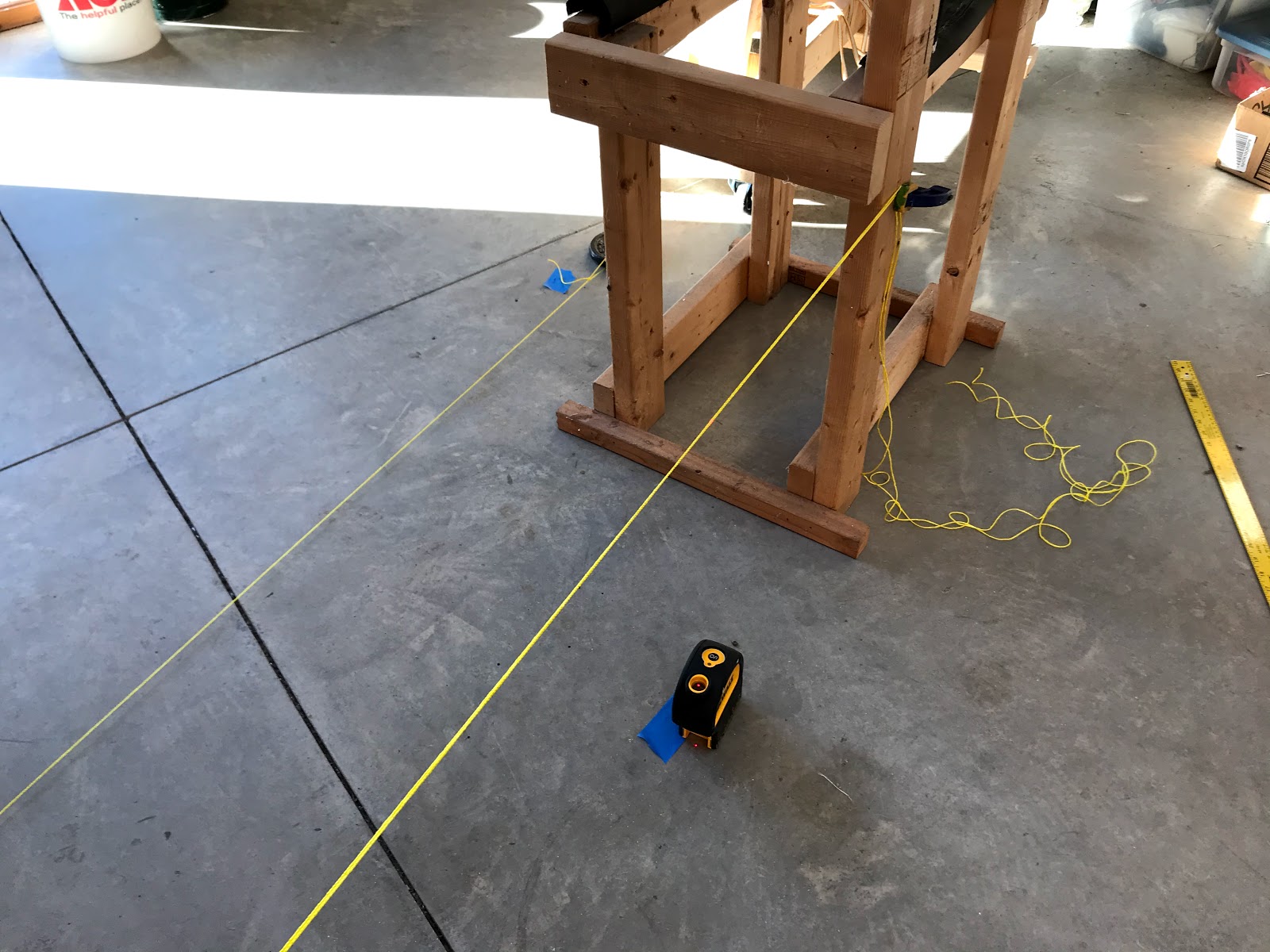
Once I trimmed the trailing edge of the gear leg fairings I put them on the landing gear and used the engine hoist (attached to the engine mount) and the tail lift to level the fuselage.  

I used my very handy laser plumb bob to mark the fuselage center line on the floor. I then marked a reference point on the gear, made a parallel mark on the floor and put a string around the fairing. With that in place I could move the fairing to line it up with the aircraft center line.

The laser plumb bob made the whole process fairly easy:


Saturday, December 14, 2019

Wingtip lights, landing gear leg fairings and parachute knockout panel


I finished a new knockout panel for the BRS parachute. I used the original panel as a template and made a new one that exactly fits my installation.

Knockout panel temporarily in place (after the parachute and rocket are installed the knockout panel is secured in place with silicone so it will easily depart the aircraft if the rocket is fired.):

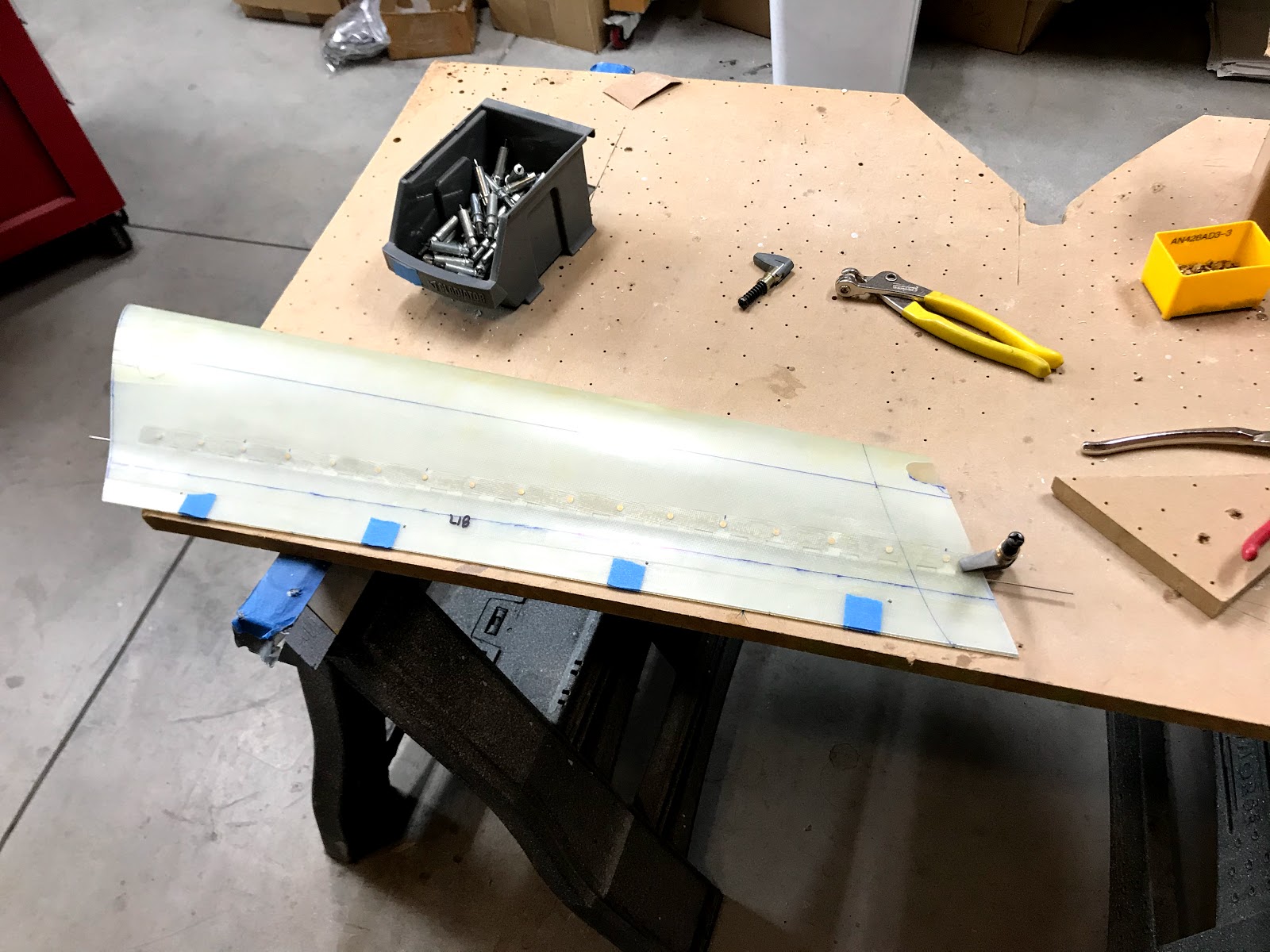
Right landing gear leg fairing hinge glued with G-flex and riveted:

Drilling the hinge to the outboard side of the right landing gear leg fairing:

I sanded down the filler I had put around the recess where the nav / strobe light lenses mount. I put some protective wrap over the lenses and stored the wingtips for now.

I reinforced the cut out area that gets clamped to the landing gear leg with one layer of fiberglass tape and G-flex epoxy.

Left fairing hinge glued and riveted:

Drilling the left fairing:

Drilling the first hinge half:


Saturday, December 7, 2019

Primed BRS fairing, more wingtips, and started on gear leg fairings

I wasn't happy with the finish on the parachute fairings from the Ekopoxy so I sanded it down and re-coated with Eastwood Aerospray  2k gray epoxy primer - much nicer finish!

Just after painting:

Turned out great, looks nice with all the tape removed:


Working on platenuts to hold wingtip lens:

Wired Deutsch DTM connectors to nav / strobe lights. I also enlarged the hole in the wingtip for these connectors.

Nav / strobe lights pictured and I also wired the tail nav / strobe.

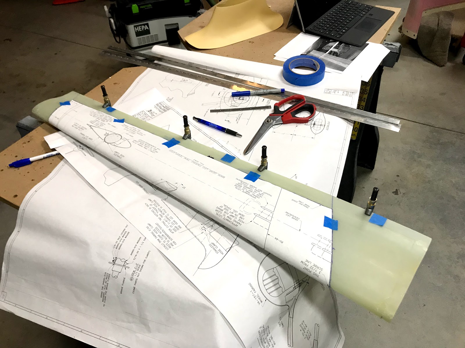
Paper template on a landing gear leg fairing: