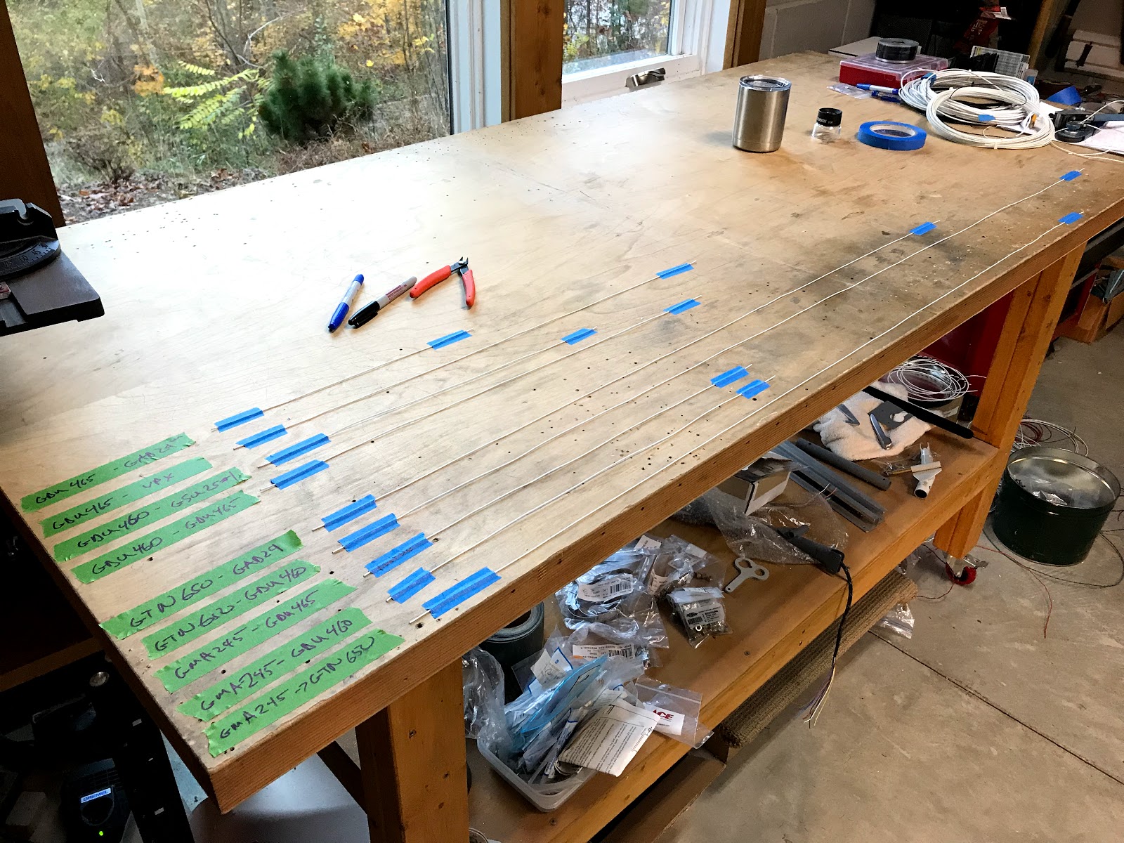
Labels

Saturday, November 18, 2017

Wire harness progress: 9 hours

The following work was done over two days:


  • Assembled connectors for GAD 29. The GAD 29 allows the GTN 650 navigator to share data with the G3X system.
  • Started wiring the two main GTN 650 connectors
  • Started wiring the two GMA 245R audio panel connectors - all of the audio panel and GTN navigator connectors use high density pins which are smaller and more of a hassle to work with.
  • Modified the CAN bus plan so I can assemble the GTN 650 connector on the bench. I have 3 devices that will to have their connectors assembled in the aircraft due to the layout of the CAN bus.
  • Connected the configuration module for the GDU 460 primary flight display. This is essentially a memory chip that is mounted inside the connector and stores all system setup data so that if you have to swap a unit out for maintenance you won't loose your aircrafts specific setup data.
  • Finished the main GDU 460 connector


Avionics wire harness so far:

GDU 460 connector (configuration module is barely visible under the right wire bundle):
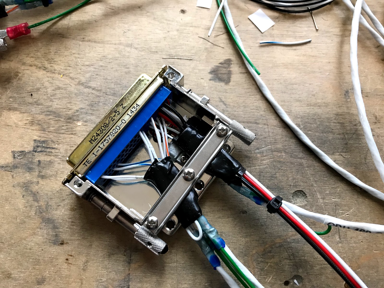
Configuration module and connector (very small wire = hard to work with):

Starting GTN 650 connectors:

Finished GAD 29 - GTN 650 interface connector:

Modified CAN bus layout:

Audio panel connectors in progress:

GAD 29 power and CAN bus connector:


Thursday, November 16, 2017

Finished GDU 450 connector: 2 hours

Finished the GDU 450 connector:
  • Added primary and secondary power wires
  • Added a ground and soldered a splice for primary and secondary pins
  • Soldered / assembled my first CAN bus node
  • Assembled back shell and shield drains

GDU 450 connector with GDL 39R connector on left:

Prior to adding back shell:

CAN bus node:

Friday, November 10, 2017

Started building the G3X wire harness: 3 hours


  • Assembled the wires and connector for the GDL 39R ADSB receiver. This connects to the GDU 450 which will be set up as the multi function display (MFD).
  • Ran the antenna cable for the vfr gps antenna for the G3X display units. All gps antennae will be mounted under the engine cowling just forward of the firewall.
  • Installed the fire sleeve on the other two firewall wiring pass through's


Harness for GDL 39R connecting to GDU 450 multi function display (MFD):

Fire proof wiring pass through's with VFR gps antenna:

Thursday, November 9, 2017

Still more wiring: 3 hours


  • Spent some time cleaning up and organizing the wires in the tunnel
  • Added pins and solder sleeves to all headset wires
  • Finished a connector for #2 ADAHRS - probably the easiest - one wire between two pins in the connector
  • Cleaned up and organized for putting together the G3X wire harness
  • Put the panel, G3X GDU 460 & 450, and GTN 650 tray in place
  • Measured wire lengths for most connections and laid them out on the bench for reference when building the harness


Ready to start putting the harness together:

If only all connectors were this easy:

Headset wires ready for connectors:

Tunnel wires looking better:

Wednesday, November 8, 2017

Fuel pump and TOGA wiring: 6 hours


  • Test fitted fuel pump and fuel lines with wiring - no problems with clearance.
  • Added a molex connector to fuel pump and ran wire from fuel pump switch and ground block to pump.
  • All wiring in the tunnel area should now be complete so I started cleaning up and organizing the wire there.
  • Soldered together the recommended two diodes to split the take off go around (TOGA) wire from the stick grip into two wires to go to the G3X (GEA24) and the GTN-650.
  • Finished my first connector for the GTN-650! It's the one with only one wire .... TOGA
  • Connected headset power wires to VPX
  • Organized headset mic and phone wires for audio panel
  • Planned next steps for building avionics wiring harness on bench


First GTN-650 connector ... also the easiest! (diodes in black shrink tube on right)

Fuel pump test fit with all tunnel wiring complete:

Fuel pump with snake skin and molex:


Tuesday, November 7, 2017

Stick grip wiring: 4 hours

I spent a fair amount of time researching and planning the best way to do the stick grip wiring with the main questions being: wiring the push to talk to the audio panel and wiring the a button for go around mode to the G3X and the GTN 650.

The push to talk turned out easy with just needing to connect to an appropriate pin on the audio panel. The go around button will need a little more work requiring two small diodes to isolate the G3X and GTN 650.

The Tosten sticks have 8 switch functions. Here is my set up: trim left, right, up, down, push to talk, auto pilot (cws, disconnect and on depending on how long you the button), take off / go around and as an experiment I will be using one button to play / pause the music going through the audio panel! (I just found this option today.)

Some more details:

  • Drilled 3 new wire pass through holes in the sub panel. I was very careful to cover and tape the electronics to keep metal shavings out.
  • Added terminals to two pieces of 5 conductor wire for the stick wiring to the panel area.
  • Ran the stick wiring forward and then temporarily attached the terminals to the switch wiring terminal block
  • Connected the trim switch wires to the VPX and attached pins to the wires going to the audio panel.

Pins ready for the audio panel:

Started the switch input connector on the VPX:

Stick grip button terminal block:

Monday, November 6, 2017

Finished wiring for heated seats: 8 hours


  • My seats from Classic Aero Designs include heating elements for the back and bottom. I committed to putting the seat heater switches on the panel early. This made the wiring a little more tricky due to the design of the seat heaters which are made for automotive after market. I spent a fair amount of time figuring out the best way to route the wires and locate the relays.
  • I ended up replacing all the connectors with micro molex and almost all the wire with mil spec tefzel.
  • The way the system is laid out requires quite a bit of wire. I ran four 18 gauge wires for each seat. 
  • I ended up locating the relays for the heaters on the fuselage floor ribs. (The relays allow for two temperature settings.)
  • The seat heaters will be a nice feature when the temps drop.
Changing out the connectors on a seat back:

Seat heater connectors and relay:

Right seat heater panel switch connector: