Labels

Monday, September 12, 2016

Stick grips: 3 hours

  • Mocked up stock control sticks with engine control bracket
  • Spent some time in the left seat making sure stick grip height will be comfortable
  • Drilled right stick assembly for c clip button to make stick removable
  • Cut down left and right control sticks for Tosten stick grips. The amount cut off of the original sticks was approximately the length of the Tosten grips plus about 5/8"
  • Checked stick travel with grips attached

Right stick grip:

Left stick grip with mocked up engine control bracket:

Drilling the left stick assembly for the c clip button:

Right removable stick assembly:


Friday, September 2, 2016

More work in cockpit: 2 hours

I went ahead and ordered the carpet for the cockpit floor and baggage area. It was fun to put the rudder pedal assembly in and figure out where I want my heel pad. I also did some work on the instrument panel such as filing and smoothing edges for a better fit. I have a few plate nuts to rivet on and I will be ready to paint the panel.

I also temporarily put the panel in place to measure clearance for the control stick grips.

Checking rudder pedal spacing for carpet heel pad:

Thursday, August 25, 2016

Wire, tube pulling and misc. 8 hours

Lots of wiring and related items going on.

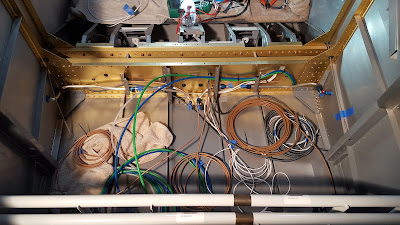
  • Drilled 2 new wiring pass through holes in spar carry through web on left and right sides
  • Drilled a few small pass through holes aft of the spar for RG-400 cable
  • Pulled AOA, pitot and static pneumatic tubes through spar carry through
  • Pulled a variety of other wires and cables through spar carry through
  • Mounted a bunch of clickbond wire tie holders on vertical surfaces
  • Mounted a bunch of wire tie holders secured with E6000 on horizontal surfaces
  • Crimped on BNC connectors for the comm radio and transponder antennae
  • Broke in the heat shrink wiring label printer
  • Mounted the fire extinguisher bracket
  • Bonded on terminal strip for Aeroled nav / strobes


Terminal strip block secured with E6000 (for Aeroled lights) and transponder RG-400 on right:

Getting more organized (clear plastic pieces are clickbond pieces being bonded):

Maybe I should have put labeled this? -Ha, It's all labeled.
Mounted fire extinguisher bracket on left carry through cover:

First use of the dymo heat shrink wiring label printer:

Crimping BNC connector witht the help of Stein's video:

Pitot, aoa, static pneumatic lines pulled and some misc cables:

Spar carry through web before start of wire pulling:

Close up of 2 new wiring pass through holes on left side:

Friday, August 19, 2016

More systems: 3 hours

  • Fabricated a bracket for an adel clamp to hold the cabin heat control cable away from the rudder pedals and fuselage
  • Installed bracket on firewall stiffener with pull rivets
  • Screwed on right side fuel line / spar cover panel bracket using #8 cap head screws - with these in place I can install snap bushings and start running wiring forward


Right side fuel line / spar cover bracket:

Approximation of heat cable clearance:

Drilling the bracket to the stiffener:

Thursday, August 18, 2016

Misc fuselage systems: 5 hours


  • Installed stainless cabin heat valve on firewall - sealed with included Rectorseal
  • Installed flap actuating weldment
  • Installed flap motor / actuator on support bracket and installed molex plug
  • Installed above in fuselage, complied with Vans flap actuator service bulletin and tested operation
  • Mounted flap position sensor and added wire tie anchors secured with e6000 adhesive
  • Researched and started fitting cabin heat cable
Flap actuator and weldment installed:

Flap position sensor and wire tie anchors:

Weldment bolted in:

Flap position sensor wire detail:

Cabin heat valve:

Thursday, August 11, 2016

Engine mount and misc. wiring: 8 hours

The following work was done over several days:

  • All engine mount holes drilled - This was actually very involved. Van's supplies the quick build fuselage with pilot holes for 4 of the 6 3/8" bolts that hold the engine mount. The problem was that all of the pilot holes were about 1/8" off. So there was a lot of making sure the mount was in the right place then opening up the pilot holes with a dremel tool with a very small grinding bit. I found a key tip online from an Asheville builder which was to use a piece of 3/8 fuel line as a drill bushing and using the mount itself as a drill guide. I have a nice 3/8" reamer to finish the holes and they all turned out great.
  • Made cutouts in bottom edge of firewall for landing gear leg clearance.
  • Started organizing wiring supplies and ordered some additional materials from Steinair along with the Garmin 245R remote audio panel.
  • Installed and tested baggage compartment LED lighting.
  • Glued on synthetic leather around headset jack area then installed headset jacks. The interior panels from Classic Aero already have a cutout for the headset jacks.

Right head set jacks:

Baggage area lighting test:

Synthetic leather glued in headset jack area:


Motor mount bolt holes done:

Lower middle holes did not have pilot holes and required spacers:

After the first hole they all went fairly quickly:

3/8 fuel tube bushing idea from another Asheville builder:

Cut out to clear landing gear legs:

Thursday, July 28, 2016

Engine mount and forward top skin: 4 hours

Now that the interior paint is done I can start working on some more interesting stuff.

I got out the engine mount and started working on getting it installed. This involved a fair amount of research online.

I also got the forward top skin out because I originally thought it need to be on when fitting the motor mount but I learned this was not required.

On a side note I decided to get a new forward top skin from Vans and work on shaping it more before I dimple it to get a better fit where it's riveted to the longerons.

Motor mount temporarily in place and working on forward top skin fit: