Labels

Tuesday, October 31, 2017

Wiring continues: 6 hours


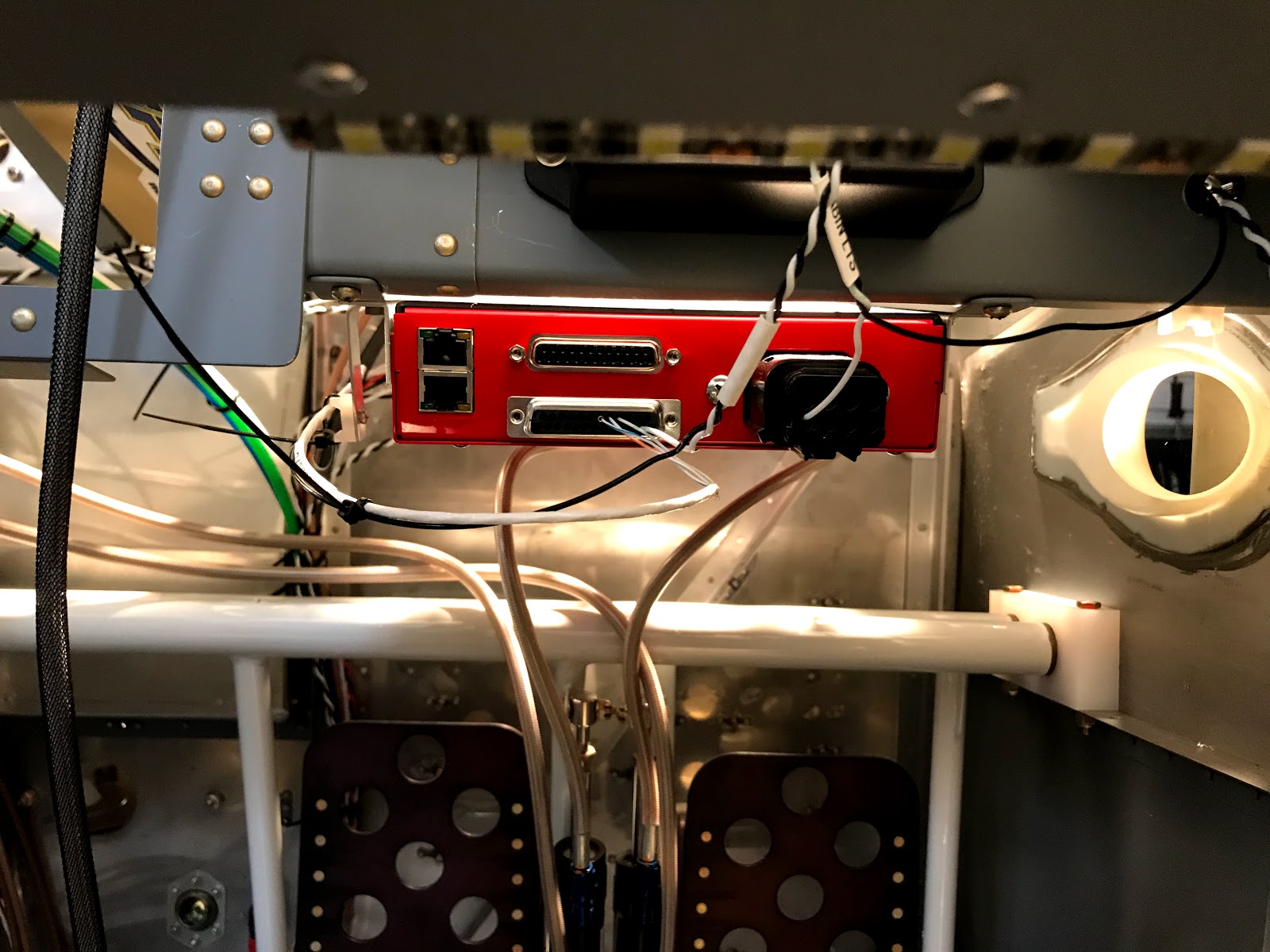
  • Mounted pins in VPX connectors - wires will need to be organized more once all are in place
  • Soldered leads on panel switches for: starter arm, push to start and auto level
  • Ran servo wire for oil cooler servo
  • Ran power wire for servo controller on panel
  • Ran wire for engine starter switches to panel and out of firewall
  • Installed fire sleeve for right firewall pass through
  • Ran power from VPX to panel fuel pump switch
Slightly more organized:

Still a lot of pins to fill on the aft facing side:

Fireproof pass through:

Auto level button soldered:

Start switches soldered:

Monday, October 30, 2017

Wiring: 8 hours

The following work was done over the last two days:

  • Drilled two new wire pass throughs in the sub panel
  • Ran the wiring for the two instrument panel 12 volt outlets. They will get usb power adapters when we are ready to fly.
  • Researched wiring required for ELT instrument panel control
  • Tested the reversing cowl flap switch and ran the wire to power the switch
  • Ran power wires for defog fans
  • Added a micro molex connector to the oil cooler servo controller
  • Replaced connectors on seat heater switches with micro molex - all seat heater wiring will be replaced with aircraft quality wire
  • Fabricated recessed mounts for under panel led lights. These are controlled by the cabin lights dimmer (which also controls the baggage lights) and should provide good light for getting in and out of the airplane at night or for use in flight.
  • Ran wires and assembled connectors for under panel lights. Lights and dimmer tested good!

Testing cabin lights (now I'm tempted to put them all over the bottom of the wings!):

Under panel recessed light mount:

Drilling the panel for the lights:

Light mounts and led strip:

New wire pass through for panel 12 volt outlet:

12 volt panel outlet wiring:

12 volt outlet test fit:

Saturday, October 28, 2017

Instrument panel work: 6 hours


  • Paul and I got most all of the switches, breakers and placards "permanently" mounted to the instrument panel. The only exception was the 4 locking toggles switches for the electronic ignition. I ran out of circular trim fittings for the toggle switches so we tried using hex nuts but we did not like the look of them. I will place an order with Steinair.
  • We did a trial fit of the panel and only had to adjust the 2 led dimmers to clear the left cockpit rib. However when we went to do a trial fit of the G3X Touch units we found that the center cockpit rib was interfering with the MFD.
  • It was useful to have another set of hands and we were able to quickly put a clearance notch in the rib to allow the MFD to fit properly.

Very happy with the look of the panel!

Circuit breakers and elt control:

Time to run more wires!

After the top skin is on pulling out the G3X units will make it easier to work behind the panel.

Thursday, October 26, 2017

Wiring and instrument panel: 4 hours


  • My brother Paul was in town for a visit and he helped me run some wires and start organizing the instrument panel.
  • We twisted and ran the wires for the taxi and landing lights, and the pitot heat. We also labeled the wires and crimped connectors on.
  • We ended up drilling another wire pass through to keep the pass through for the left stick grip wiring from filling up.
  • A good deal of time was spent using small files and the dremel to clean paint out of ALL the openings on the instrument panel.
  • We also pop riveted the ELT control to the panel and started installing the backup circuit breakers.


Circuit breaker placard and ELT control:

Taxi light and pitot heat wires (new pass through hole is under control stick mount):

Tunnel is filling up!

Landing light wires:

More wires ready to connect to VPX:

Using the new Shorai battery balancer / charger (thanks Paul!) to put the batteries in "storage" mode:

Tuesday, October 10, 2017

Wiring: 8+ hours

The following work was done over several days:

  • Finished drilling wire pass through holes in cockpit floor ribs
  • Did a fair amount of research and planning for wiring the G3X and VPX
  • Ran wires for Aeroled nav / strobe lights back from VPX to cockpit floor terminal block. I also crimped on ring terminals and used my solder sleeves for the first time to connect the wire shield to the terminal block.
  • Ran RG-400 for left wingtip nav antenna connection, also crimped on fitting
  • Ran flap position sensor wire, connected to sensor and secured sensor and motor wires


The central tunnel is starting to get crowded:

Flap motor power wiring ready for VPX connector (I like the heat shrink label printer but I almost prefer the labels on the wire but not shrunk - you can see each example here):

Wiring connected and secured for flap motor and position sensor:

Nav radio antenna connector (on the right):

Terminal block for Aeroled nav / strobe lights (the wing nav / strobe lights will also connect here):

The Garmin G3X Touch wiring diagram looks fairly simple:

Wiring pass through holes in floor ribs: